


Gears are a key component in a wide range of motion control devices, as well as in mechanical and electromechanical transmissions. In this article we discuss the key elements that will help you with the design of gears for your projects. More specifically, we will focus on their terminology, gear formulas, and even aspects related to gear design that will help you prevent premature failures and perform an optimal gear calculation. Let’s begin!
In a myriad of applications, geared transmissions are in charge of transferring the right torque provided by a motor, being, in fact, the most reliable, strong and resilient transmission systems. In addition, they stand out due to the great efficiency with which they deliver power, limiting energy loss as a result of a lower friction between its surfaces.
What types of gears stand out in today’s industry?
- Those that operate on parallel shafts mounted on a pinion: spur gears, helical gears, double helical gears, epicycloid gears, etc.
- Those that operate on transmissions that have perpendicular shafts (helical gears that rely on a worm screw for torque transmission).
- Bevel gears which transfer motion rotationally on converging shafts.
Knowing how different types of gears work is key when opting for one or another in your industrial projects. In line with this, it is paramount to analyse in-depth how the gear and the flanks of the pinion’s tooth engage when designing a smooth rotational transmission (maintaining a constant angular speed). This is the heart of the matter when it comes to gear calculation. In order to face this complex process, let’s begin by properly establishing the most critical terminology regarding gears:
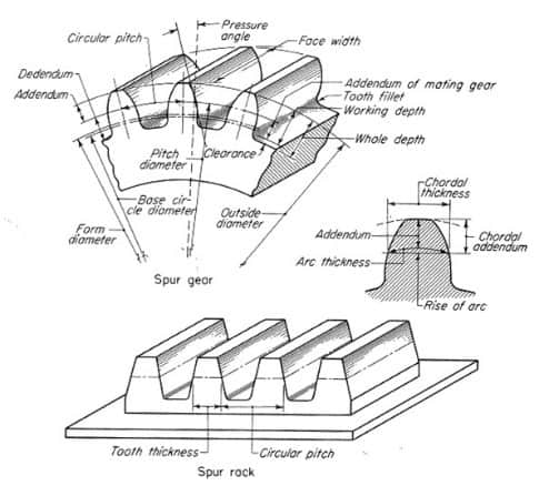
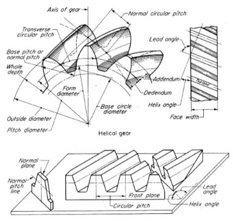
Gears terminology
- Gear ratio: It is basically the relation between rotational speeds of two meshed gears, where one of them exerts a force on the other. This ratio results from the difference in diameters of both gears, giving the name ‘pinion’ to the one of the smallest diameter. Basically, this factor implies a rotational speed difference between the two shafts. Therefore, and keeping in mind the engagement of gear and pinion, the gear ratio is calculated using the number of teeth on the gear divided by the number of teeth on its pinion.
- Pitch diameter: Found based on the number of teeth and the centre distance the gears operate at.
- Base pitch: Pitch as measured at the base circle where the involute starts.
- Centre distance: Equivalent to the sum of the pinion’s pitch diameter and the gear’s pitch diameter, divided by two.
- Circular pitch: Circular distance between a point on a tooth in a gear and a point on the next tooth, as measured along the pitch circle. Two gears must have the same pitch circle in order to engage with each other.
- Diametral pitch (module): A standard measure for gear teeth. It is the number of teeth per inch of the pitch diameter. Increasing the size of the teeth reduces the diametral pitch. Generally, diametral pitches range between 25 and 1.
- Mounting distance (D): It is the distance between the point where the shaft of the gear and the line of the pitch angle intersect, and a point of reference on the gear. Respecting this distance implies ensuring a proper mounting and use of the toothed components.
- Pressure angle (angle of obliquity): The slope of a gear’s tooth at the diametral pitch. If the pressure angle is 0, the tooth is parallel to the shaft of the gear, which makes it a spur gear.
- Helix angle: The longitudinal inclination of the tooth. When the helix angle is 0 degrees, the tooth is parallel to the shaft of the gear, which means we would also be referring to a spur gear.
Being familiar with these concepts is fundamental for a proper gear calculation. Next, now that these matters are defined, we will be able to discuss the types of gears that best fit our transmission. It is important to pay attention to the properties or features of each of them.
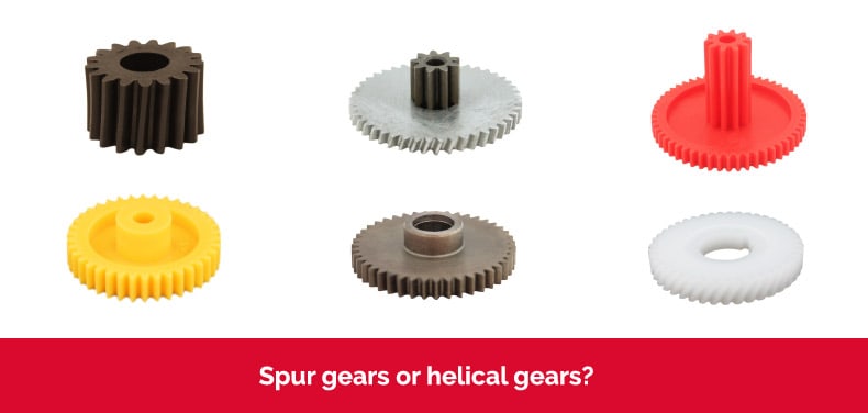
You might be interested in: “Spur gears or helical gears?“
Tips for gear calculation and design
At this point, it is best to remember that gears are highly standardised, both when it comes to their teeth, and to their size. In this regard, the American Gear Manufacturers Association (AGMA) publishes standards for designing, manufacturing and mounting gears.
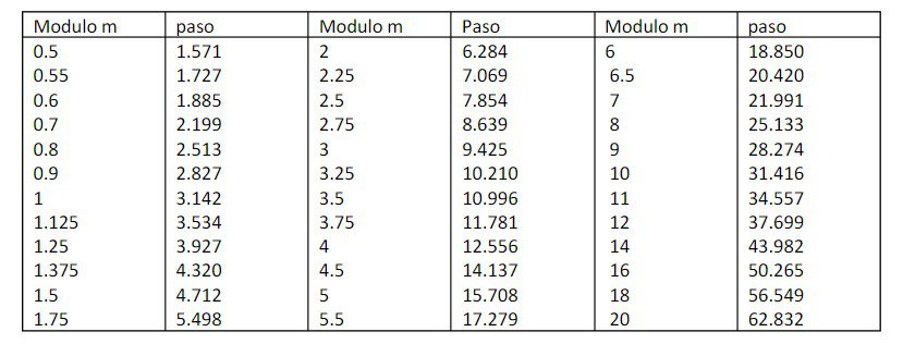
Table of standard gear modules and pitches (UNE 3121)
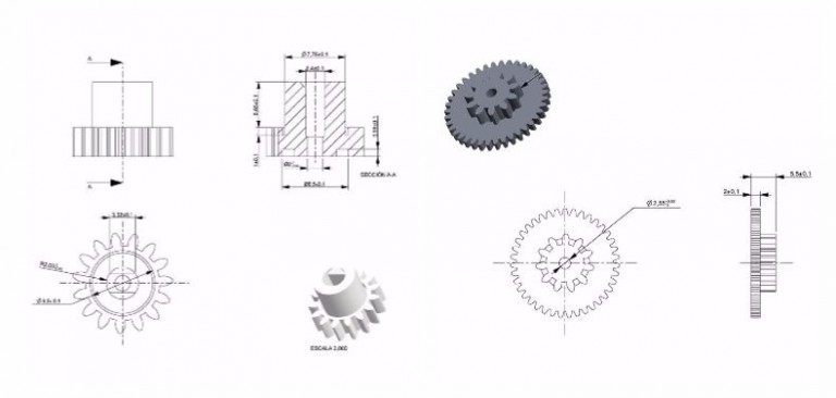
Generally, design and calculation revolve around these key elements:
- Number of teeth (Z): A fundamental value for the gear.
- Pitch diameter (Dp): Another key element of the gear, and the starting point for transmission calculations. Its value is related to the number of teeth (Z) and the gear’s module.
- Module (M): This parameter identifies a group of gears, and tooth and gear sizes are based on this value.
- Outside Diameter (De): A distance as measured between the tips of two diametrically opposed teeth. Its value depends on (Z), (M) and the pitch angle.
- Pitch (P): The distance between equal points of two consecutive teeth as measured on the pitch circle. If we multiply the pitch (P) by (Z) we will obtain the value of the pitch diameter (Dp).
- Face angle (Beta): Angle as measured from the pitch angle to the outside of the gear. This angle depends on the pitch angle and (Z).
- Root angle (Gama): Value specified in tables based on the face angle.
- Pitch angle (Alfa): Angle used when designing the gear and on which the pitch circle (Dp) is located. Its value is related to the gear ratio, being 45° in a 1:1 gear ratio.
- Mounting distance (D): It is the distance between the point where the shaft of the gear and the line of the pitch angle intersect, and a point of reference on the gear. By respecting this distance we will ensure an optimal mounting and tooth use.
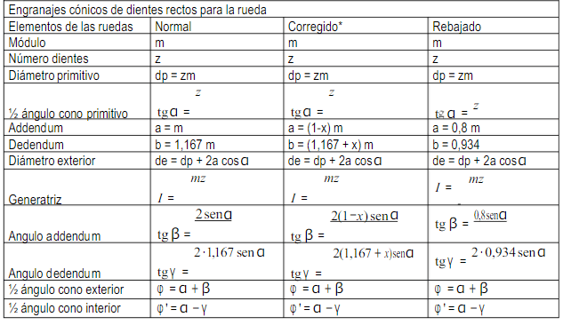
Main gear formulas
Situations that cause gears to fail
- Insufficient resistance to bending or contact force, which causes teeth to fail.
- Poor design, as a result of manufacturing errors, which causes an inadequate load ratio between 2 or more pairs of gear teeth.
- Problems related to vibration: Whenever the base pitch of the meshing gear and pinion are different from the operating base pitch of the pair of gears, there is excessive vibration and noise. This inadequate operation will also affect the service life of the gear.
CLR, over 40 years manufacturing gears for industry
All of the problems discussed can be solved if the gears are properly designed, manufactured and mounted. At CLR we have a long track record in gear design and calculation for various applications. Whether plastic or metal gears, our technology and team of mechanical engineers work towards achieving that each component offers the best results in your actuators and mechanical transmissions.
Gear manufacturing at CLR


An excellent look at how you need to calculate gears correctly for the best levels of precision