


The design of drive shafts is usually one of the most critical processes in the design of speed reducers. Are you about to undertake a project and are unsure about the procedure to follow to drive shaft design? In the post below we bring you the steps to follow when designing drive shafts and other shafts.
In mechanical engineering, and axisymmetric object that is especially designed to transfer power is known as a drive shaft.
Shafts are used to support immobile, oscillating or rotational parts of machines, but they do not transfer any angular momentum, and are therefore subject to flexion.
Likewise, a drive shaft is a shaft that transfers torque and is subject to torsional loads. This is the result of the transmission of a couple and it may at the same time be subject to other types of mechanical stress.
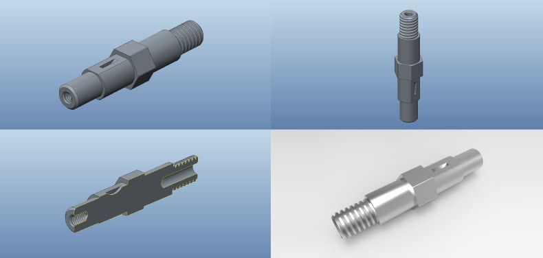
The typical shaft layout is a stepped element with a circular cross-section, with a wider cross-section at the centre so that several elements can be mounted on it at its ends, which results in a greater section modulus at the central area where flexion causes greater loads.
Drive shaft design phases
1. Define the required angular speed and transmission power specifications.
2. Select its configuration, in other words, choose the elements that will be mounted on the shaft for the desired power transmission and choose the attachment system for each of these elements to the shaft.
The construction design consists of determining the lengths and diameters of each section or step, as well as the selection of the attachment method for the parts that are to be mounted on the shaft. During this stage, the following aspects need to be taken into account, among others:
- Ease of mounting, dismounting and maintenance.
- Shafts need to be compact in both length and diameter in order to reduce the amount of material.
- Allow for an easy securing of the parts on the shaft in order to prevent undesired motions.
- Measures should preferably be standard.
- Prevent discontinuities and sudden cross-section changes.
- Generally, shafts are staggered in order to better accommodate parts.
- Shafts are only supported by two supports so as to reduce alignment issues.
- Place the parts near the supports in order to reduce bending moments.
3. Decide on the overall shape of the shaft geometry when mounting the elements selected.
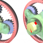
4. Determine the loads on the various elements that are mounted on the shaft. Power transmission elements such as spur gears and pulleys transmit radial, axial and tangential forces. Due to these types of loads, different stresses are caused on the shaft:
- Flexion
- Torsion
- Axial load
- Shear
5. Calculate the reaction forces on the supports.
6. Calculate the loads on any section. Loads are the internal reactions caused on a section of a solid as a result of external forces applied to it.
7. Select the shaft material and its finishing. The most widespread is steel, and a low or medium-carbon low-cost steel is recommended. If strength conditions are more demanding than those of rigidity, higher strength steels may be chosen.
8. Select the proper safety factor based on the manner in which the load is applied.
9. Locate and analyse critical points based on the geometry and loads calculated.
10. Verify their strength:– Static – Fatigue– Dynamic loads
11. Verify the shaft rigidity:– Deflection due to bending and elasticity slope – Deformation due to torsionThe shafts must be rigid enough to prevent excessive deformation from hindering the proper operation of the phat are mounted on them.Likewise, the (rolling or sliding) bearings may be affected if the shaft slopes where the bearings are located are too sharp. Since steels essentially have the same modulus of elasticity, shaft rigidity should be controlled by means of geometric decisions.
12. Verify deformations.
13. Verify the critical speed.
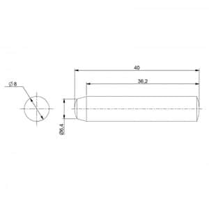
14. Find the final sizes that fit the commercial sizes of the elements mounted on the shaft.In addition to these stages, here are a few recommendations to keep in mind during shaft design:
- Shafts have to be as short as possible in order to avoid high bending stress. To that same end, support bearings should be placed as close as possible to high loads.
- Try to avoid a stress concentration by using generous fillet radii in section changes.
- In order to prevent vibration issues, fast-turning shafts require a good dynamic balance, good fastening at the supports and a rigid configuration.
- Hollow shafts perform better in regard to vibrations, though they are more expensive to manufacture and have a greater diameter.
- Rigidity is usually the most critical factor when designing shafts, and steel is used in order to prevent it.
“By keeping all of these items in mind, the shaft development process will be optimised, preventing early failures, deformations and other issues”
CLR, Compañía Levantina de Reductores, seeks the best solution to your company’s driving mechanisms. Do you need help? Our engineering team will assist you until you find the best, strongest and most efficient geometries and parts for your actuators and gear boxes. Do you need advice for a transmission project? Do you have problems with the shaft of your speed reducer? We can help.

Nice information. Keep up the good work.