Driveshaft design: deformations and problems
El diseño de ejes de transmisión o árboles de transmisión suele ser uno de los procesos más críticos en el diseño de reductores de velocidad. ¿Te vas a embarcar en un proyecto y no sabes qué procedimiento seguir para diseñar los ejes? En el siguiente post te damos los pasos a seguir para el diseño de ejes y árboles de transmisión.
El design of driveshaft or driveshaft is usually one of the most critical processes in the design of speed reducers. Are you going to embark on a project and you don't know what procedure to follow to design the axes? In the next post we give you the steps to follow for the design of axles and driveshaft.
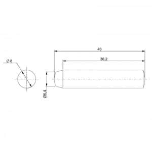
In mechanical engineering It is known as driveshaft or driveshaft To everything axisymmetric object specially designed to transmit wattage.The shafts are used to support immovable, oscillating or rotating machine parts, but they do not transmit any rotational moments, so they are generally subject to flexion. In the same way, an driveshaft It is a shaft that transmits a motor force and is subject to torsional stress. This is due to the transmission of a couple of forces and may be subject to other types of mechanical stress at the same time. typical configuration of an axle It is that of an element with a staggered circular section, with a larger section in the center, so that the different elements can be mounted on it at the ends, which provides a greater resistant section in the central area, where flexion causes the greatest efforts.
Phases in the design of driveshaft
- Define the rotational speed and transmission power specifications necessary.
- Select your setup, that is, choosing the elements that will be mounted on the shaft for the desired power transmission and choosing the system for attaching each of these elements to the shaft. El constructive design consists in determining the lengths and diameters of the different sections or steps, as well as in selecting the methods for fixing the parts to be mounted on the tree. At this stage, the following aspects must be taken into account, among others:
- Easy assembly, disassembly and maintenance.
- The axes have to be compact to reduce material both in length and diameter.
- Allow easy attachment of the parts to the shaft or axle to prevent undesirable movements.
- The measurements should preferably be normalized.
- Avoid discontinuities and sudden section changes.
- Generally, the trees are built staggered for the best positioning of the pieces.
- In order to reduce alignment problems, the axes are supported on only two supports.
- Place the parts close to the supports to reduce bending moments.
- Propose the General form for the geometry of the axis when assembling the chosen elements.
- Determine the pains on the different elements that are mounted on the axle. Power transmission elements such as sprockets, pulleys and stars transmit radial, axial and tangential forces to the shafts. Because of these types of loads, different types of stress generally occur on the shaft:
- By flexion
- Torsion
- Axial load
- Cutting
- Calculate the reactions on the supports.
- Calculate the requests in any section. Stresses are the internal reactions that occur in a section of a solid as a result of external forces applied to it.
- Select the material of the shaft and its finish. The most used is the steel and it is recommended to select low or medium carbon, low-cost steel. If the strength conditions are more demanding than those of stiffness, higher-strength steels could be chosen.
- Select the adequate safety factor, depending on the way in which the load is applied.
- Locate and analyze critical points depending on the geometry and the calculated loads.
- Verify your stamina:- Static - To the fatigue - To dynamic loads
- Verify the stiffness of the tree:- Deflection due to flexion and slope of the elastic - Torsional deformationThe shafts must have sufficient stiffness, in order to prevent excessive deformations from affecting the proper functioning of the parts that are mounted on them. On the other hand, the bearings (with rolling or sliding contact) can be affected if the slopes of the shaft at the bearing sites are very large. Since steels have essentially the same elastic modulus, the stiffness of the trees must be controlled by geometric decisions.
- Check the deformations.
- Check the critical speed.
- Determine the definitive dimensions that conform to the commercial dimensions of the elements mounted on the axle. In addition to these phases, some recommendations that must be taken into account when designing axles are:
- Attempts will be made to avoid stress concentrations by means of generous radii of agreement in the changes of section.
- The axes must be as short as possible to avoid high bending stresses. For the same purpose, the bearings and support bearings shall be placed as close as possible to high loads.
- In order to avoid vibration problems, quick-turning shafts require good dynamic balancing, good fixation of the supports and a rigid configuration.
- Hollow trees improve vibration behavior, although they are more expensive to manufacture and have a larger diameter.
- Stiffness is often the most critical factor in tree design and steels will be used to avoid it.
“Taking into account the above, the axle development process will be optimized, avoiding faults, deformations and other problems”
CLR, Levantine Reducer Company, is looking for the best solution to displacement mechanisms of your company. Do you need help? Our engineering equipment will guide you to find the most ideal, resistant and efficient geometries and parts in your actuators and gearboxes. Do you need advice with a transmission project? Are you having problems with the shaft of your reducer? We can help you.

We offer customized, tailor-made solutions. Configure with us the perfect gearmotor for your project.
¿Tienes un proyecto en mente?
We can manufacture your tailor-made solution, we accompany you at every stage of the project to offer the solution that best suits your application.
Do you have a project in mind?
We can manufacture your tailor-made solution, we accompany you at every stage of the project to offer the solution that best suits your application.
