


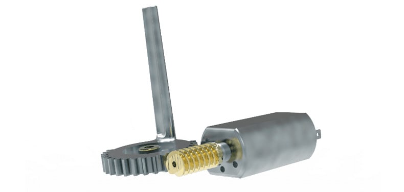
In a myriad of projects involving motion control mechanisms, and mechanical or electromechanical transmissions, gears are a key component, which is why it is essential to know how to calculate the gear ratio for their optimal performance.
Are you undertaking a project involving gears, but don’t know how to calculate their gear ratio? Don’t miss this post, in it we will explain what this ratio is all about and the formulas to calculate it. Let’s get to it!
First and foremost, you should know that the gear ratio consists of the relationship between the rotational speeds of two interconnected gears, where one of them exerts a force on the other.
This relationship is the result of the difference in diameter of the two gears, which implies a difference between the rotational velocities of both shafts, which can be verified through the concept of angular velocity.
Likewise, the gear ratio of a gear box describes the relationship between the revolutions per minute (rpm) of the input shaft and the rpm of the output shaft, whether with the purpose of multiplying the torque, reducing the speed, or both.
Formulas to calculate the gear ratio
Before calculating the gear ratio in your project, it is paramount to know the speed and output torque you want to obtain in the speed reducer and the speed and input torque you have to begin with.
Once both numbers are known, the formulas to calculate it are:
i= Ws/ We = Ze/ Zs
i (Gear ratio)
Ws (Output velocity)
We (Input velocity)
Ze(number of teeth in the driver gears)
Zs(number of teeth in the driven gears).
Ms= Me * u/ i
Ms (Output torque)
Me (Input torque)
u (Performance)
i (Gear ratio)
The gear ratio is calculated by dividing the velocities or by dividing the number of teeth of the drive gears by the driven gears.
In torque calculations a performance is always implied, which will vary depending on the material the gears are made out of, the stages, lubrication, etc. Therefore, the closer the calculated performance is to the real one, the closer we will be to the required data.
In most cases, an output velocity is usually required, which is calculated by knowing the input velocity and depends on the stages that the speed reducer has.
This gear layout is also linked to the space available for the speed reducer, which is why finding a gear layout depends on many factors, such as available space, input data (motor to be used), the torque to be withstood by those gears (which will give you the size and depth of the gears), etc.
It is of utmost importance to keep all of these factors in mind, since the final design of the speed reducer being as expected will depend on them. For example, if you need a speed reducer to drive a spring in vending machines, you will need the maximum dimensions of the speed reducer (height, length, width), an output torque (minimum force that it should be able to exert in order to move that spring and the item that the rail of the vending machine contains) and a speed for that the product is not shot out, among other requirements.
Let’s see a practical example:
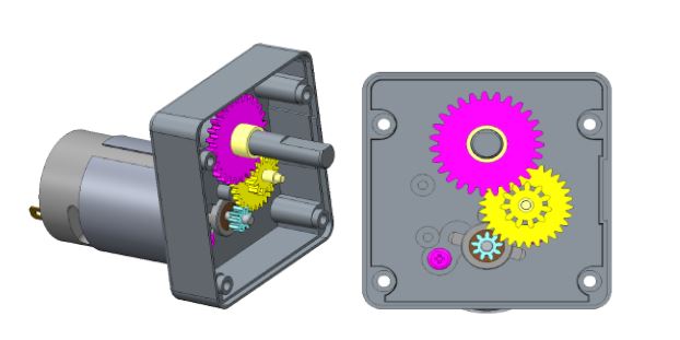
Drive gear (driver)(blue): Z9
Gear (driven)(yellow): Z30
Pinion (driver)(yellow): Z11
Final gear (driven): Z27
i= 9*11/ 30*27= 0.12222
The speed reduction is the inverse of the gear ratio.
Speed reduction= 1/i= 8,18
Supposing that the motor has about 7,000 r.p.m. (revolutions per minute), with this transmission we will be able to know the output velocity.
i*We= Ws
Ws= 7,000 * 0.12222= 855 r.p.m
This means that when the output shaft rotates once, the motor will have performed 855 revolutions.
The design of that speed reducer will be result of studying all previous items and answering questions such as, how many gears should we add to accomplish that speed? Which material should they be made out of? Size? or, which engine should we use so that by using the least number of gears we can accomplish the desired values?
With all of this information we will be able to perform the study, a painstaking and complex task, since their design depends on fulfilling a number of parameters, which makes it paramount to have a reliable supplier that assists you in every stage of your project and helps you find personalized solutions, guaranteeing a maximum quality.

This is really interesting, you’re an exceptionally effective blogger. I’ve enrolled with your feed and also, look ahead to reading your wonderful write-ups. What’s more, we have shared your internet site inside our social networks.