We could consider speed reducers as a major invention which, without a doubt, see a greater notoriety and presence in current times, being used in practically every machine around us. But what are the main applications of speed reducers? What elements are they composed of?
What are the main applications of speed reducers?
Speed reducers are used to operate all types of industrial and household machines which need to reduce the speed of an electric motor safely and efficiently. Speed reducers adjust a motor’s speed in order to provide the torque needed by a machine to work properly.
As a transmission system, speed reducer gearboxes stand out due to their high complexity, with a myriad of speed reducer system designs available depending on the needs and specifications of each application.
This eBook may be interesting to you: “Gear Motors: Choosing the best one for each project”
Elements that compose a speed reducer
Knowing about certain concepts will help us better understand the elements that compose a speed reducer.
- The concept of torque
It is a rotational force expressed in units of kilogram per metre, Newton per metre or pound per feet. When torque is combined with an execution time, it turns into a “power”.
- Electric motor
An electric motor has a specific force specified in HP, and has an operational speed for the output shaft. Both characteristics, power and speed, define the torque the motor can provide. The torque will determine whether a load will turn or not.
The combination of power, torque and speed of a motor or gear motor is defined as per the following formula:
Mechanical Power
W= M (Nm) x w (rad/s).
W =16,4 Nm (maximum torque output in Nm) x speed (at maximum output in rad/s).
10 r.p.m = 10× 1 revoluciónmin×1 min60 s×2π rad1 revolución= 10 x 2 x π60= 1,047 rad/s
W =16,4 Nm x 1,047 rad/s= 17 W.
1cv= 735,39875W = 0.98632HP
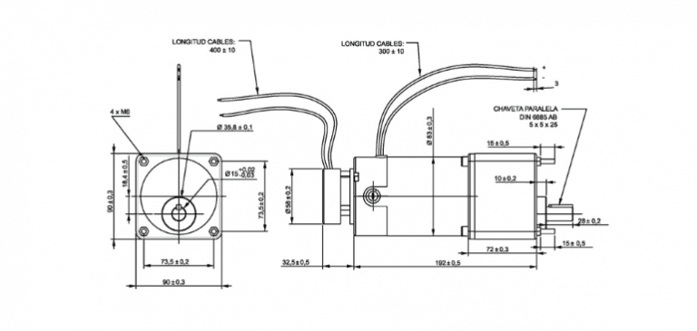
- Gearbox: It is a transmission mechanism. It is composed of a set of mechanical components that enable the proper speed reduction and increase in torque transmission. All of its items are just as important, and they need a perfect geometry and composition for the proper operation of the system. We are referring to gears, plain bearings, crown wheels, washers, pulleys, pinions…
Overall, before starting an electromechanical engineering project that requires an actuation, we should answer questions that are vital to obtain an optimal final outcome. Being aware of the types of speed reducers and their advantages is important. The selection will depend on the type of motion we seek, the power we require, or the space we have in the machine. Here we show you the main types of speed reducers you can find.
Types of speed reducers
Due to its great precision and reliability, many automatic transmissions nowadays use this type of speed reducer.
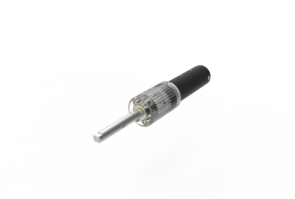
Which elements compose a planetary speed reducer?
- Sun: The central gear. It is larger and rotates around the central shaft.
- Carrier: Its purpose is to hold up to 3 satellite gears of the same size which engage with the central gear, a.k.a. sun.
- Ring gear: An external ring (with teeth on its inner side) engages with the satellites and encloses the entire epicyclic gear train. Additionally, the central shaft may also become the rotational centre for the outer ring, which makes it easy to change directions.
Gear reducers
Spur
It is the most common type of gear, and its main feature is that its teeth are set up on parallel axes. This type of spur gear is used when motion has to be transferred from one shaft to another one that is close and parallel.
These are its features
- Used for transferring a great amount of power (around 500 KW)
- Provides a constant and stable speed ratio.
- It is more efficient when compared to a helical gear with the same size.
Helical
They run smoother and more silently when compared to spur gears; this is because of the oblique manner in which their teeth interact in relation to the rotation axis. They can be set up parallel to each other or, generally, at 90 degrees. If this is the case, and helical gears are crossed, they are combined with a worm gear.
What are its features?
- It lasts longer; and is ideal for high load applications.
- Its angled teeth operate gradually, allowing the operation of the gear to be smoother and more silent.
- Load is distributed across several shafts, resulting in less wear.

Classification of gear motors based on the disposition of their shafts
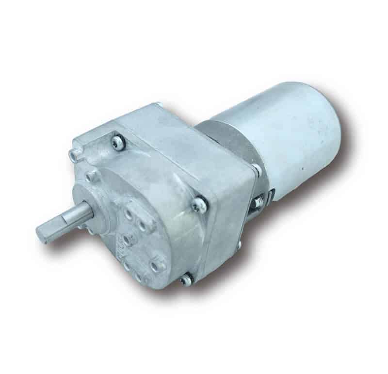
Parallel shaft gear motors
This is a type of gear motor that uses gears to accomplish an optimal speed reduction. The shaft of the motor and the gear motor are in parallel axes; this disposition allows for very flat gearboxes.
The parallel shaft gear motor can use three types of gears to accomplish the transmission; choosing one or the other will depend on the final application.
What are the advantages of a parallel shaft gear motor?
- A compact design, which translates into a lower weight and smaller space
- They reach powers of up to 200 KW.
- Low vibration, low noise levels.
Worm / 90-degree gear motor
This can be considered as the simplest gear motor; it is composed of a toothed worm wheel, normally made of bronze with a steel shaft in its centre. This wheel is constantly in contact with a steel screw shaped as a worm (hence its name). One of its main features is that its shafts are set up in a 90-degree angle.

How can the operation of gear motors be improved?
There are some basic parameters which allow for a better quality product or solution based on their analysis.
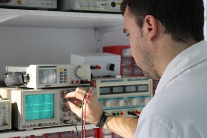
The analysis and correction of mechanical noise levels
Gear motors should be subjected to tests using frequency measurement equipment before their release on the market. It is very important to take note of mechanical vibrations and for your gear motor supplier to know how to use vibration measurement instruments to prevent uncomfortable frequencies.
Optimal torque measurement
The optimal measurement of the starting torque, output torque and rated torque guarantees the proper transmission of the motion and the adaptability of the machine or application.
Power consumption
Energy efficiency of the speed reducer is another item to keep in mind when choosing one model or the other. The disposition of the gear train, the disposition and characteristics of rolling bearings or the surface treatments of components enhance performance across the entire system.
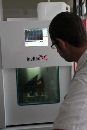
Service life tests
Tests are carried out in laboratories to measure the resistance, limits and the speed reducer service life. Gear motor suppliers that have these laboratories and the testing technologies they offer can guarantee buyers the delivery of quality gear motors.
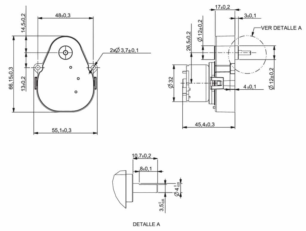
Speed reducers design
Before delving into the particulars of gear motor design, we will mention the service factor, which is a reference to the conditions that affect or increase the power demands of a gear motor. This factor may be related to dust and relative humidity, the amount of vibration to withstand, or the quantity of operation cycles, among other factors. Reducing the influence of the service factor is the result of having a deep knowledge of the inner workings of the reducer and improving the design of its entire transmission mechanism.
After studying the operation to be carried out, gear motor manufacturers can design a transmission system that optimises output power. Here you can find some technical elements which may prevent loss of energy, thereby increasing the motor’s lifespan.
Some examples would be:
- Use and placement of rolling bearings
Within geared systems, the use of rolling bearings offers a reduction of friction between the many moving parts, thus considerably reducing loss of energy.
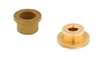
- Use of self-lubricated plain bearings
This type of parts reduce friction to a lower extent than rolling bearings do. Still, they minimise loss of resilience to axial motions.
- Gear design (tooth size, placement…)
Spur gears placed on parallel axes are the type of gear that produce the least loss of efficiency. Several modifications can be made to the teeth to increase their efficiency, but it will depend on each specific case.
- Use of vibration-limiting components
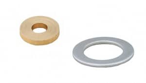
Several solutions can be applied to reduce vibrations, such as the use of rolling bearings, washers, plain bearings… Application of all of these items will improve the proper operation of the gear motor in the long run. It will be more precise, less noisy, and will suffer less wear as a result of limited vibration levels.
Importance of materials and lifespan
In addition to the design, the quality of materials and specific treatments that each part is subjected to will likewise lengthen its resilience and lifespan. Here, for example, there are treatments that are capable of increasing the thermal resilience of parts to increase their heat dissipation inside a gearbox.
Speaking about the inherent characteristics of material, it is advisable to always have present the requirements of the application (number of stages, r.p.m., output power, etc.) so as to choose the material which performs optimally within each project.
There are several materials that may improve a gear motor’s efficiency, such as self-lubricating or low-friction plastics. These types of materials increase efficiency but diminish lifespan. Each particular case should be studied to determine which material is to be more beneficial in relation to workloads and other aspects.
When working with metals, we can apply treatments for metal materials to increase the hardness and resilience of parts, and to protect them against external agents. These types of treatments do not prevent loss of energy between gears, but they can drastically increase the parts’ lifespan.
It is most important to choose the proper type of internal lubrication for each working environment. In this way, we will make sure that the mechanism is properly lubricated throughout its lifespan.
CLR, a leader in speed reducer manufacturing
CLR, Compañía Levantina de Reductores designs, industrialises and manufactures speed reducers for a myriad of industrial applications. Complying with the highest quality standards of each sector, CLR accompanies you on every stage of your project, from design to the final implementation. Put your trust in a one-stop supplier that is able to face any challenge that may emerge.
This is a brief example of our work